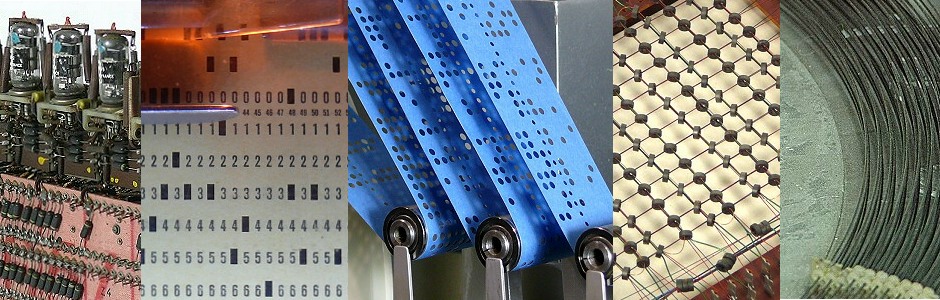
Historic internal storage media
In the following some types of memory are described which are found in the computers on display at the technikum29. These devices may be classified as either RAM (random access memory) or ROM (read only memory). Due to their respective size these are very demonstrative examples.
The problem of storing information is of central importance for digital computers and was a difficult area during the early days of computing. In these times building a fast processor was considerably more easy than building an equally fast and large memory system for this processor. This led to some rather arcane solutions which are completely extinct today.
Nowadays as well as 50 years ago, these characteristical attributes are important:
- cycle time
- packing density
- costs / bit
- (thermal) power loss
Storages are classified geometrically:
- one-dimensional alignment (e.g. the delay line memory)
- two-dimensional alignment (e.g. drom storage, disk storage)
- three-dimensional alignment (e.g. core memory, the number of layers is the word length)
These physical principles has been used: electrostatic charge (storage tube), propagation of acoustic waves (delay line memories), ferromagnetism (core memory, plated wire memory, drum/disk memory), holography (optical memories). The most important and most spread memories are the ferromagnetic memories.
Delay line memory from the BULL GAMMA 3 tube calculator
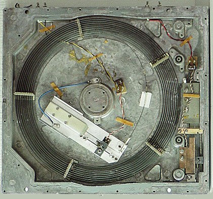
Incredibly big, next to no capacity from today's point of view and at 8.3 kg extremely heavy - that is the historic memory from our vacuum tube based BULL GAMMA 3 computer (vintage 1952-1959). See this marvelous device here:
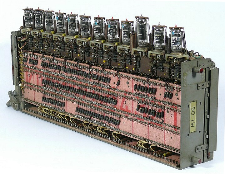
Figure 1: Delay-Line
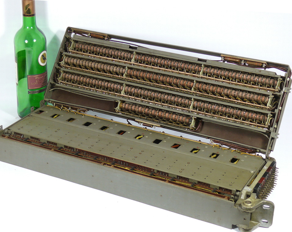
Figure 2 (on the left): Delay line memory opened
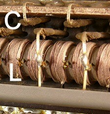
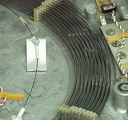
Figure 3: Cutout. The LC elements can be clearly seen
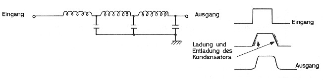
Figure 4: Part of a delay line - three of 120 LC combinations are visible
This kind of memory is extremely rare and predates the widespread use of core-memory. It was called a "delay-line memory". The BULL GAMMA 3 uses seven of these delay-line memories, corresponding to 58 kg of electronics yielding a total of 42 bytes of main memory.
Magnetostrictive memory
1 kB magnetostrictive delay line memory
Another kind of "delay line" memory is the so called magnetostrictive memory. This technique is based on the idea of the propagation of ultrasonic waves through a thin wire. The information to be stored is fed into a long wire by the effect of magnetostricion (the wire contracts when exposed to a strong magnetic field – this in turn yields an acoustic wave traveling across the wire). A bit pattern created by this effect travels along the wire to its end where the information is picked up by a piezo electric element. The output of this pickup will be amplified and fed back into the beginning of the wire loop.
This basically yields a sequential storage circuit - an impulse pattern will run in an endless loop through the wire. To insert information into the loop some (simple) additional circuitry is necessary. To delete bits, the feedback loop will be opened while setting bits requires an OR gate at the input of the wire loop.
This type of memory is volatile and has a rather long access time – on the other hand, its capacity depends mainly on the length of the wire and the basic clock of the surrounding circuitry so it may easily expanded. In addition to this it is relatively inexpensive and rugged making it suitable for applications like desktop calculators and the like.
Core memory
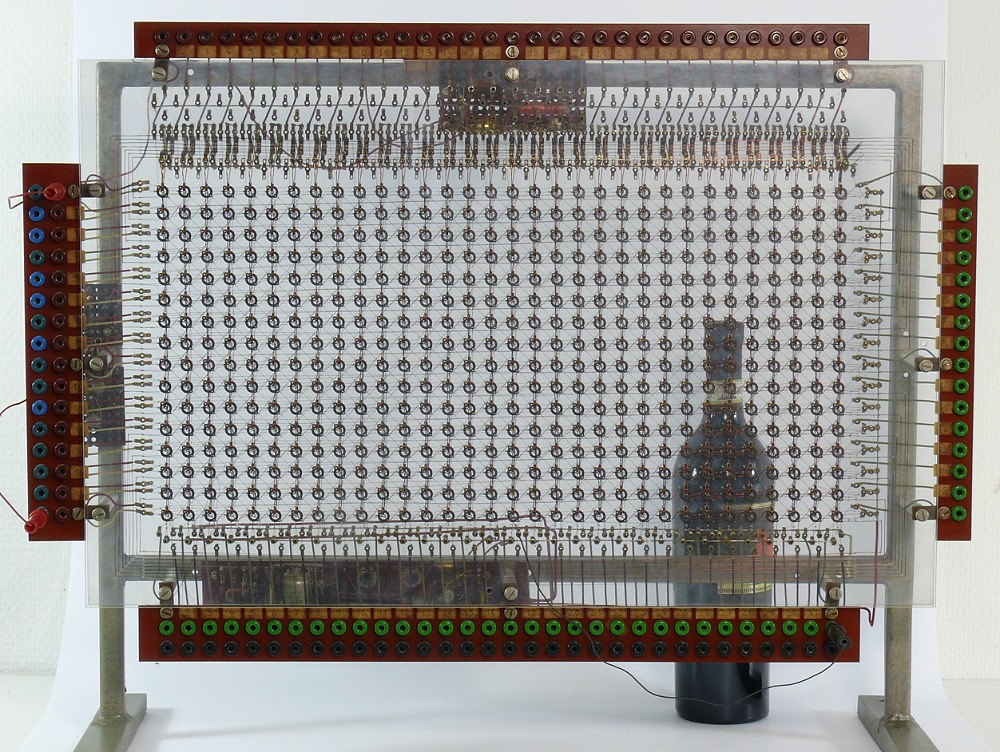
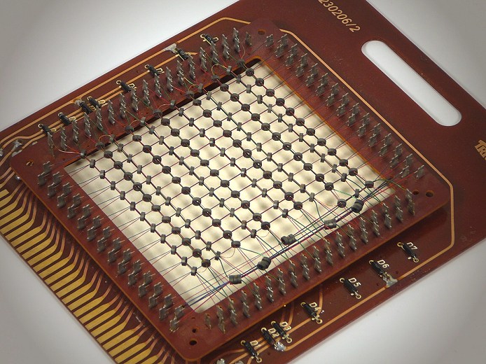
Core memory demonstration model, Transfluxor
(you can enlarge the picture!)
This giant core memory has been used for teaching purposes in a university in
the late 1950s and early 1960s. It is a fully functional model of a special
type of core memory. Its size can be estimated by means of the wine bottle
visible in the background.
In contrast to the more common "core memory" store used in most computers until
the advent of semiconductor memory, this device uses so-called Transfluxor
cores with a diameter of 8.5mm. These have a very peculiar shape - not the
simple donut structure of a traditional core. This results in a separation of
magnetic flux domains which allows a non-destructive read out - a definitive
advantage over traditional core-memories. Alas, this comes at a cost: The
control of such a memory system is more complicated compared with a traditional
core memory. Nevertheless it was used in telecommunications equipment like
telephone exchanges.
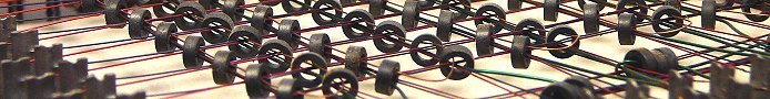
The creation of this demonstration device must have required an awful amount of
time. Having a look at this detailed view of the memory gives an impression of its complexity. Each Transfluxor has two holes through which thin wires are threaded.
Triumph core memory
The company "Triumph" created a very demonstrative core memory about 1961). The circuit card, measuring 16 cm by 20 cm, can store 144 bit which equals 12 machine words of 12 bits each (which was a common word length in this time). Thus a single bit occupies an area of about 2.2 square centimeters.
Another core memory made in 1969 is shown here. It is used in the high speed printer of the UNIVAC mainframe and stores a single line of text to be printed (132 characters). The individual cores can still be seen by the naked eye.
Storage layer with a capacity of 16.000 bit
During the years the capacity of core memory devices was increased more and more while the dimensions were shrinked accordingly. This picture shows a core memory plane made in the time frame 1975 - 1978. The area shown equals that of the 144 bit memory by Triumph shown earlier. Now there are more than 16000 cores on the same area. The individual cores can only be seen with the aid of a magnifying glass. The whole core memory block contains 16 planes like this containing more than 256000 single cores (this is equivalent to 32 kB of data) occupying a volume of about 2.5 cubic decimeters. This device marks the end of the era of core memory.
The smaller the individual cores the faster the access time – this device features an access time of only 200 ns. One drawback of core memory is that reading the information stored in a row of cores destroys the information. So every read access has to be followed by a write access to retain the information (reading from a core memory takes more time than writing to the memory which is a rather unique "feature" of this technology).
A major advantage of core memory is its non-volatility. The information stored in a core memory will be retained even when power is lost. It is possible to turn on a machine switched off in 1975 and continue operation at the very same step where it ended in 1975. Even today main memory is sometimes called "core" which is a reminiscence of the early days of computing when memory was in fact core memory. A memory dump as a result of a program crash is still called "core dump" in the UNIX operating systems family, for example.
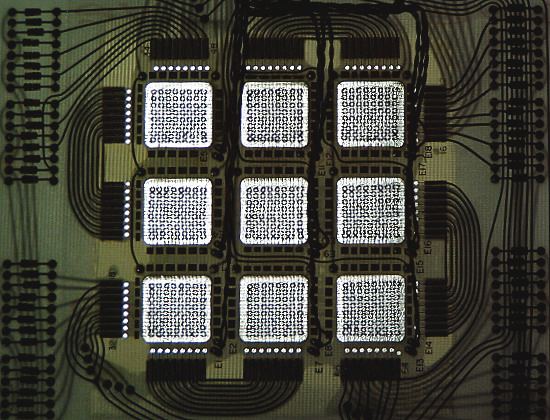
Threaded ROM
Nixdorf threaded ROM
All of the memory devices shown before were capable of read and write operations. Sometimes a read only memory (ROM for short) is needed. The picture shows such a ROM made in the mid 1960s which is closely related to a core memory.
The device shown is from a NIXDORF-WANDERER Logatronic system (made in 1966 approximately) which is a predecessor of the well known NIXDORF 820 system (see below). This ROM can store 2048 words of 18 bits each. The implementation is a true masterpiece of its time.
You can get further explanations and a more detailed version by clicking on the picture.
Magnetic stick memory
Nixdorf magnetic stick memory
NIXDORF decided to implement a read only memory which could be easily modified by customers and did not require a service technician to modify its contents.The whole operating system of the NIXDORF 820 was stored in ROMs like this (all in all 3 modules – type 177 – were necessary for this). Even empty ROMs were manufactured which were sold to customers who liked to modify their 820 system. Each of these modules could hold 4096 word of 18 bits each. One of these ROMs weighs 2.4 kg.
Clicking on the picture will yield a more detailed version of it.
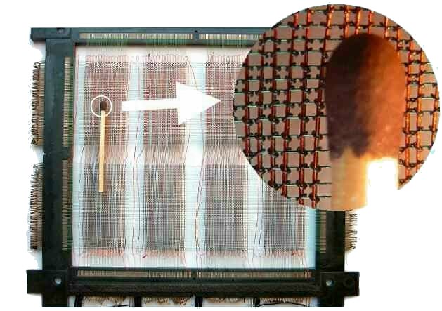
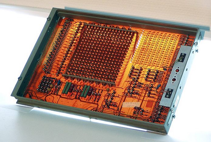
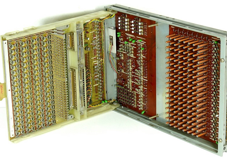
Plated wire storage
The plated wire storage was intended for replacing the core memory. Our UNIVAC 9300 is equipped with this type of memory that was initially announced by UNIVAC for the new UNIVAC 9000 series as a "technical revolution" in their magazine "The punch card" in 1967.
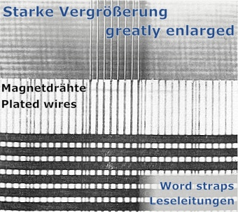
While research and development in the Goddard Space Flight Center of the US space
program, NASA, the american government closed a deal with UNIVAC to develop a
storage medium with a total input power less than 1 Watt, non-destructive readout
(that is, no more neccessarity to write the informations after reading them),
high capacity, low cycle time and functionality in a temperature range from
-20° C to +50°C (-4°F to 122°F).
In this way the plated wire storage was developed, based on a couple of ingenious ideas. It found its application, among others, in space probes. Voyager I and II are equipped with plated wire memory.
Clicking on the photography will yield further informations about the design of the plated wire storage.
Two channel punched tape
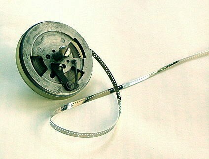
As already described before (section programmable 2nd generation desktop calculators), the DIEHL Combitron calculator used a time delay memory (like the magnetostrictive memory described elsewhere). Since this type of memory is volatile, DIEHL needed a non-volatile memory for the overall control of the machine. This had been implemented using a two channel punched tape. The first channel serves as a clock channel while the second channel contains the actual control data.
During the startup of the calculator, the contents of this punched tape were copied to the time delay memory which then took over control of the machine.