Measurement and Experimental technology
Measurement and Experimental technology can link Communication and Computer Technology. Measurement technology has a long history and there have been nice and remarkable devices.
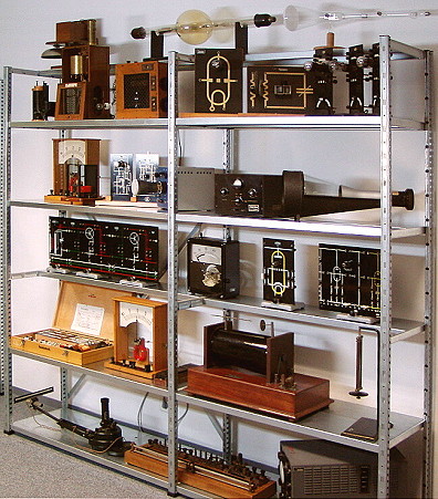
This picture shows some devices from the "experimental physics" area. You
will probably note the use of "natural" materials (wood, glass, metal) and the
well-designed very simplified interface that makes comprehension simple.
We will go into detail for some of the devices shown on the left.
Galvanometer
This is a remarkably functional, big and beautiful all-purpose measurement device made by Siemens & Halske (about 1905). At that time even simple objects of utility were made with lovely details. This device was used as an auxiliary device for morsing purposes in the national administration of the German Empire.
In 1891, this beautiful galvanometer was purchased from Hartmann & Braun (Frankfurt/Main, Germany) and offered in catalogs. The principle is simple: in the underlying coil (green) flows the current to be measured, which builds a magnetic field. In this field sits a very sensitive compass needle which is hung up on a thin wire. The longer and thinner the torsion wire, the more sensitive the device.
Measuring was then an art that had to be mastered. Particularly disturbs the Earth's magnetic field, so that a correct positioning were only able by experts.
Until the invention of measurement amplifiers, measuring very small voltages
and currents was a big problem. To do that job, moving coil devices had to be
very sensitive. This was realized with a moving coil that was mounted on a
torsion wire. The reflecting mirror at the lower end of the wire was spotted by
a light ray, so the whole composition acts like a very long "light needle".
By this way very long needle lengths (multiple meters) could be simulated.
Such a galvanometer must be set up absolutely horizontally and vibration-free.
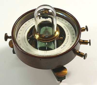
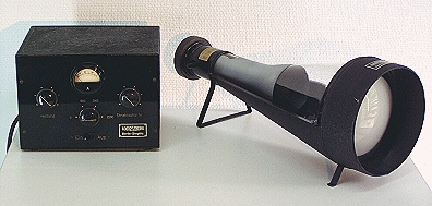
The Mirror Galvanometer by Hartmann & Braun is
a simple and functional demonstration model from the 1920s.
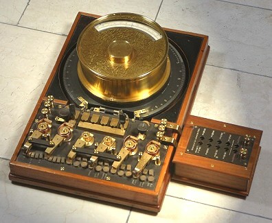
Radio engineering
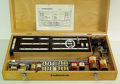
With the NEVA radio technology system, students could do challenging experiments like measuring the wave lengths in the VHF area with the Lecher lines.
Cathode Ray Tubes
Before television and oscilloscopes, the Cathode Ray Tube was a sensation, especially in schools. This was one of the very first experiments where students could see that electrons have almost no inertia, so they can be deflected easily in the presence of an electric field. This tube (with power supply on the left) from the German company Loewe is an historical piece from the 1930s. It measures about 50 cm!
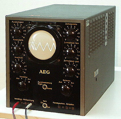
After the currency reform in West Germany, the production of mesurement devices got going again. This AEG oscilloscope was built in 1949. It seems to be an exact replica from an AEG device of the late thirties. It is equipped with steel tubes that were put on the German market at 1938. Neither the time base of the horizontal deflection nor the amplitude of the vertical deflection are calibrated by the manufacturer. To measure absolutely with this device, you always need reference sizes.
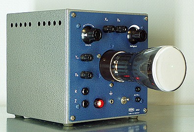
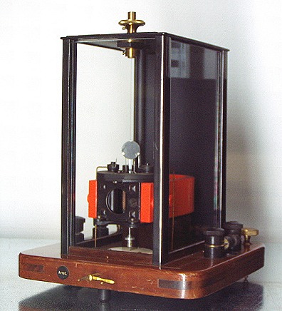
The "Physikalischen Werkstätten" (phsyical facilities), Phywe, built this small oscilloscope for demonstration purposes. It can be used to show the electromagnetic interaction of an electron beam in E/B fields. Since (CRT driven) television was not yet a mass medium, these experiments were state-of-art in those days.
TEKTRONIX Oszilloscopes
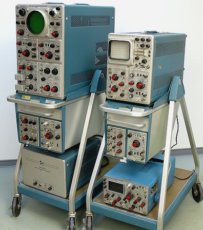
In the heyday of pulse technology as used in radar and computing the development of high performance oscilloscopes was necessary. This is where an Oregan based company named Tektronix Inc. made a name for themselves. Their products are examples of high precision measurement equipment showing great workmanship and extraordinary performance. In addition to that Tektronix oscilloscopes
came with service manuals that are a joy to read and a source of knowledge in electronic circuit design. Over the years Tektronix oscilloscopes became the epitome of high quality commercial oscilloscopes nearly unrivaled by other companies.
On the left hand side the truly gigantic Tektronix Type 555 oscilloscope is shown. The oscilloscope sitting next to it is a Type 564 which is also quite big but does not compare with the 555.
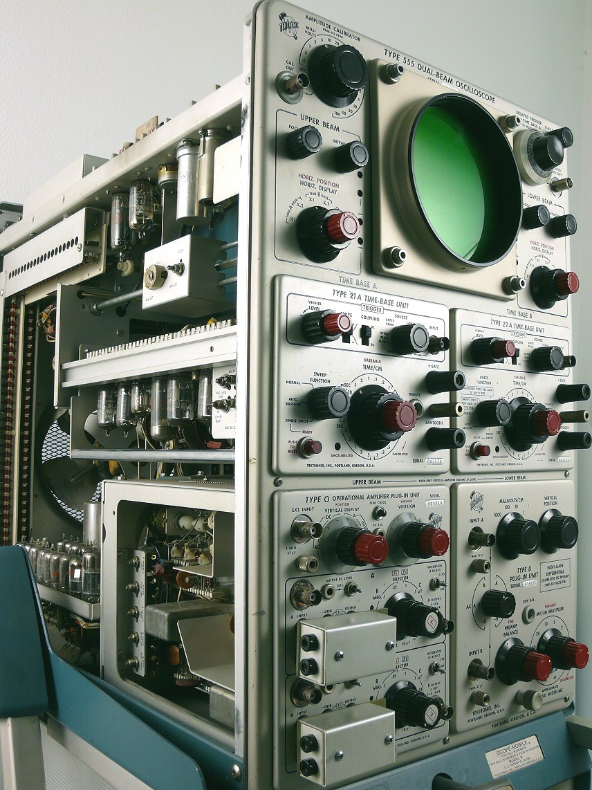
The Type 555 was first sold in 1963 and is a true dual-beam oscilloscope with two individual time bases. This makes it superior compared with traditional dual-channel oscilloscopes with only a single time base and an electronic chopper for the dual-channel display.
The 555 features a separate power supply which is sitting on the bottom of the oscilloscope cart (a scope mobile). All in all the 555 contains about 100 tubes - an extraordinary amount for such a device. As a result the power requirement of the 555 is quite high with about 1 kW.
The maximum signal frequency that can be displayed with the 555 is 33 MHz - an outstanding value for the time. Oscilloscopes like the 555 were normally carried from one place to another on a cart (it is next to impossible for a single person to lift such a device). Therefore the scope mobile often had storage space for additional modules that were not regularly used.
The 555 on display is in mint condition---a rare circumstance since most oscilloscopes from this time show signs of their heavy duty use. A high resolution picture of the 555 can be seen here.
The Type 564 oscilloscope on the scope mobile on the right uses a bistable storage tube---a technology that was not mature at this time. These tubes were characterized by a short lifetime. Most notably the brightness of the display decreased rapidly with time and the maximum beam velocity for
storing images was about 500 cm/ms.
Below the 564 is a Tektronix Type 453 - a small oscilloscope which is quite difficult to service and repair due to its small physical size. By the way: Modern Tektronix oscilloscopes offer bandwidths up to 80GHz!
Digital experience system
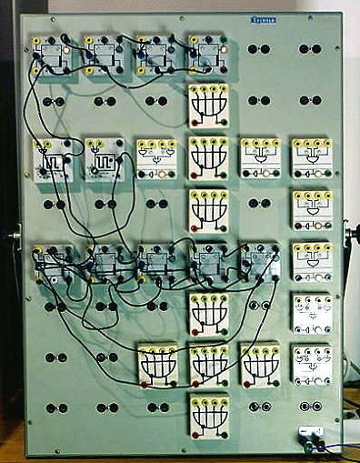
This big white board is an experience system from Leybold from the early 1970s. At that time, the subject "digital electronics" was taught in schools. Students could set up logic systems like binary counters, full adders, flip-flops, multiplexers, etc. This was quite fascinating for students at that time. Today, in ordinary schools, there is no more time for electronics in the curriculum.
The world of electronical calculating
Calculating requires counting
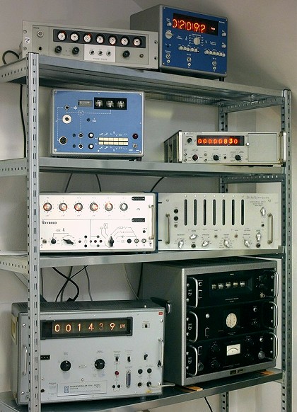
Last but not least, we show a composition of (frequency) counters from
different epoches. There are, among others, devices equipped with tubes (57
electron tubes) or discrete transistor logic (mostly germanium).
The different counting tubes (e.g. E1T or GC10B) and the very different
display types are quite impressive.